Hardware
2. CAD Files
2.2. Descriptions
2.2.1. Antenna Holders
Mounting arms that hold the main antenna end for extending and retracting
Reflector Antenna holders
Central mount that attaches to the top of the center encoder to hold the main anatennas
2.2.2. Bracket Holders
Bracket of Raspberry Pi that can be mounted by sliding in and out of a mounting position
Bracket of HackRF that can be mounted by sliding in and out of a mounting position
2.2.3. Circuit Case
Bracket of Circuit Case that can be mounted by sliding in and out of a mounting position
Custom case of PCB
2.2.4. Encoder Mounts
Reflector Encoder Mount
Main Antenna Encoder Mount
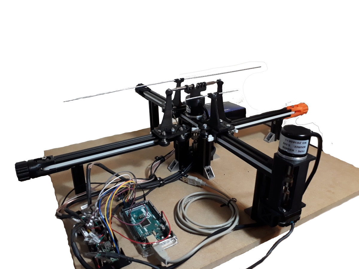
2.2.5. Main Antenna Assembly
These combine to make a fully assembled base of the Main Antenna
2.2.6. Microphone Holders
Similar to Antenna arms, these parts are for holding the 2 opposite pointing electret microphones in order to scan for sounds and sound origins
mic_support_1.STL [Main Antenna Holder] (x1)mic_support_2.STL [Reflector Holders] (x2)mic_support_3.STL [Main Antenna Holder (lowest sitting rail)] (x1)
2.2.7. Microswitch Mounts
These mounts hold the microswitches for homing function
Microswitch_mount.STL [Holders for Main Antenna Microswitches] (x2)Microswitch_mount_reflector.STL [Holders for Reflector Microswitches] (x2)
2.2.8. Motor Holders
These are for holding the motors in place
motor_bracket_3.STL [Main Antenna Motor Holder]new_motor_mount.STL [Reflector Antenna Motor Holder]Main Antenna Motor Brace that mounts the Main Antenna Motor Holder to the rail
2.2.9. V-Rails
Longer legs that hold the higher section of the Main Antenna Track
V-Rail_long_leg.STL (x2)Shorter legs that hold the lower section of the Main Antenna Track
V-Rail_short_leg.STL (x2)V-Rail that the Carriage Plate uses to guide the Main Antennas (27 cm)
V-Rail_track.STL (x2)Legs that hold the Reflector Antenna Track and will act as motor and microswitch mounting
V-Rail that the Carriage Plate uses to guide the Reflector Antennas
V_Rail_track_2.STL (x2)
2.2.10. V-Wheel Assembly
Creality X Carriage Plate (the plate used by the belt drive on the rail systems to move the antennas)
These parts combines with the Creality X Carriage Plate to create the complete V-Wheel Assembly
2.2.11. Wiring Channel
Channel that guides small groups of wire into position
2.2.12. Rotary Encoder
Stand-in model for the rotary encoders being used
3. Electrical Components
3.1 Circuit Components
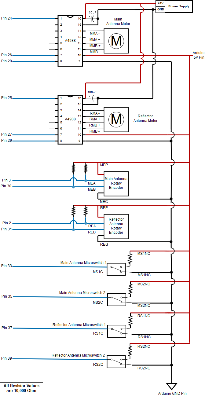
- Pololu A4988 Motor Driver
- Nema 17 Bi-polar 0.9 Degree Stepper Motor [17HM08-1204S]
- Incremental Photoelectric Rotary Encoder 400 P/R [SEN0230]
- SPDT Omron Microswitch
3.2 Software Defined Radio
3.3 Power Supply
- AC/DC Adadpter - 24VDC 2.5A [RPR-2402A5-P5]
4. Circuit Diagrams
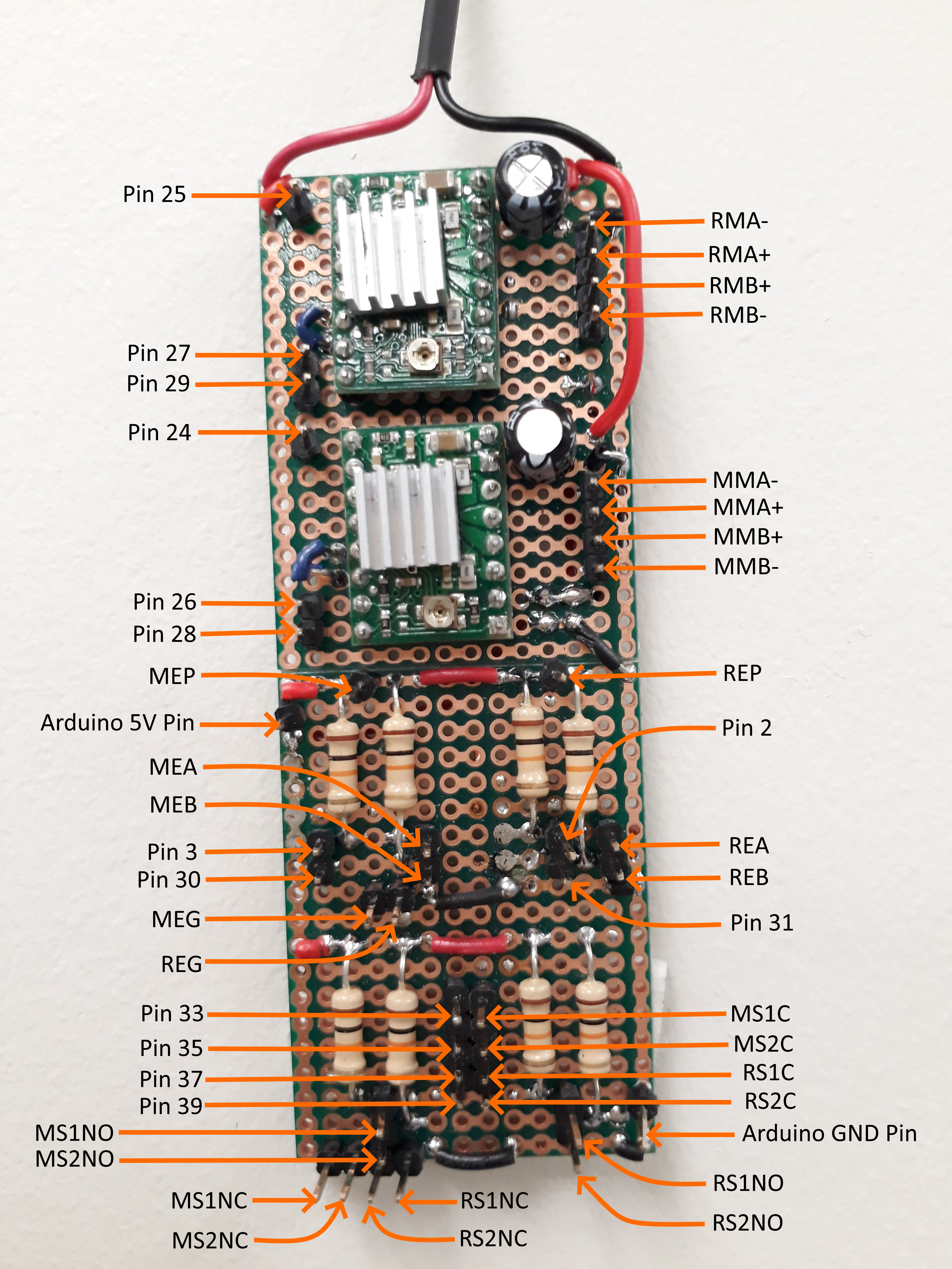
4.1. Label Definition
| Label Name | Description: |
|---|---|
| MMA - | Main Antenna Motor Coil 1 Negative Lead (Black) |
| MMA + | Main Antenna Motor Coil 1 Positive Lead (Green) |
| MMB + | Main Antenna Motor Coil 2 Positive Lead (Red) |
| MMB - | Main Antenna Motor Coil 2 Negative Lead (Blue) |
| RMA - | Reflector Antenna Motor Coil 1 Negative Lead (Black) |
| RMA + | Reflector Antenna Motor Coil 1 Positive Lead (Greed) |
| RMB + | Reflector Antenna Motor Coil 2 Positive Lead (Red) |
| RMB - | Reflector Antenna Motor Coil 2 Negative Lead (Blue) |
| MEP | Main Antenna Encoder Power Pin (White) |
| MEA | Main Antenna Encoder A Pin (Red) |
| MEB | Main Antenna Encoder B Pin (Green) |
| MEG | Main Antenna Encoder Ground Pin (Black) |
| REP | Reflector Antenna Encoder Power Pin (White) |
| REA | Reflector Antenna Encoder A Pin (Red) |
| REB | Reflector Antenna Encoder B Pin (Green) |
| REG | Reflector Antenna Encoder Ground Pin (Black) |
| MS1NO | Main Antenna Microswitch 1 Normally Open Contact |
| MS1NC | Main Antenna Microswitch 1 Normally Closed Contact |
| MS1C | Main Antenna Microswitch 1 Common Contact |
| MS2NO | Main Antenna Microswitch 2 Normally Open Contact |
| MS2NC | Main Antenna Microswitch 2 Normally Closed Contact |
| MS2C | Main Antenna Microswitch 2 Common Contact |
| RS1NO | Reflector Antenna Microswitch 1 Normally Open Contact |
| RS1NC | Reflector Antenna Microswitch 1 Normally Closed Contact |
| RS1C | Reflector Antenna Microswitch 1 Common Contact |
| RS2NO | Reflector Antenna Microswitch 2 Normally Open Contact |
| RS2NC | Reflector Antenna Microswitch 2 Normally Closed Contact |
| RS2C | Reflector Antenna Microswitch 2 Common Contact |
4.2. Circuit Schematics
4.3. Wiring Diagram